Mechanical Drawing Legend Symbols . You will find that there is no industry standard and that symbols can vary. P&id symbols are a graphical representation of physical equipment installed on the field. Also listed in the notes section is any. There are few iso and british standards available that. Basic types of symbols used in engineering drawings are countersink, counterbore, spotface, depth, radius, and diameter. There should be a legend of symbols on the mechanical drawings. State the five types of information provided in the title block of an engineering drawing. State how the grid system on an. The notes and legends section of a drawing lists and explains any special symbols and conventions used on the drawing, as illustrated below. Mechanical drawing symbols are standardized graphical representations used on blueprints to indicate the geometry and function.
from designscad.com
You will find that there is no industry standard and that symbols can vary. The notes and legends section of a drawing lists and explains any special symbols and conventions used on the drawing, as illustrated below. Also listed in the notes section is any. P&id symbols are a graphical representation of physical equipment installed on the field. Basic types of symbols used in engineering drawings are countersink, counterbore, spotface, depth, radius, and diameter. Mechanical drawing symbols are standardized graphical representations used on blueprints to indicate the geometry and function. There should be a legend of symbols on the mechanical drawings. State how the grid system on an. There are few iso and british standards available that. State the five types of information provided in the title block of an engineering drawing.
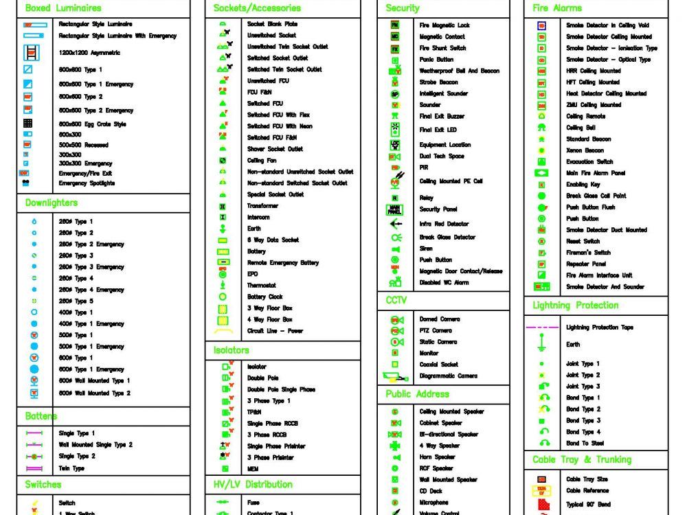
Electrical Legend ( With Symbols ) • Designs CAD
Mechanical Drawing Legend Symbols Mechanical drawing symbols are standardized graphical representations used on blueprints to indicate the geometry and function. State how the grid system on an. There should be a legend of symbols on the mechanical drawings. Also listed in the notes section is any. State the five types of information provided in the title block of an engineering drawing. There are few iso and british standards available that. P&id symbols are a graphical representation of physical equipment installed on the field. The notes and legends section of a drawing lists and explains any special symbols and conventions used on the drawing, as illustrated below. You will find that there is no industry standard and that symbols can vary. Mechanical drawing symbols are standardized graphical representations used on blueprints to indicate the geometry and function. Basic types of symbols used in engineering drawings are countersink, counterbore, spotface, depth, radius, and diameter.
From www.pinterest.es
Piping Coordination System Mechanical symbols for Isometric drawings Mechanical Drawing Legend Symbols State the five types of information provided in the title block of an engineering drawing. Basic types of symbols used in engineering drawings are countersink, counterbore, spotface, depth, radius, and diameter. Mechanical drawing symbols are standardized graphical representations used on blueprints to indicate the geometry and function. The notes and legends section of a drawing lists and explains any special. Mechanical Drawing Legend Symbols.
From www.linecad.com
ELECTRICAL LEGEND SINGLE LINE & SCHEMATIC SYMBOLS Free CAD Block And Mechanical Drawing Legend Symbols P&id symbols are a graphical representation of physical equipment installed on the field. Basic types of symbols used in engineering drawings are countersink, counterbore, spotface, depth, radius, and diameter. There should be a legend of symbols on the mechanical drawings. Also listed in the notes section is any. The notes and legends section of a drawing lists and explains any. Mechanical Drawing Legend Symbols.
From enginedbtersanctus.z22.web.core.windows.net
P And I D Diagram Symbols Mechanical Drawing Legend Symbols Also listed in the notes section is any. P&id symbols are a graphical representation of physical equipment installed on the field. Basic types of symbols used in engineering drawings are countersink, counterbore, spotface, depth, radius, and diameter. The notes and legends section of a drawing lists and explains any special symbols and conventions used on the drawing, as illustrated below.. Mechanical Drawing Legend Symbols.
From mavink.com
Mechanical Drawing Legend Mechanical Drawing Legend Symbols You will find that there is no industry standard and that symbols can vary. There are few iso and british standards available that. There should be a legend of symbols on the mechanical drawings. Also listed in the notes section is any. The notes and legends section of a drawing lists and explains any special symbols and conventions used on. Mechanical Drawing Legend Symbols.
From designscad.com
Mechanical Drawing Legends DWG Block for AutoCAD • Designs CAD Mechanical Drawing Legend Symbols The notes and legends section of a drawing lists and explains any special symbols and conventions used on the drawing, as illustrated below. Basic types of symbols used in engineering drawings are countersink, counterbore, spotface, depth, radius, and diameter. There should be a legend of symbols on the mechanical drawings. State how the grid system on an. P&id symbols are. Mechanical Drawing Legend Symbols.
From www.linecad.com
ELECTRICAL LEGEND AutoCAD Free CAD Block Symbol And CAD Drawing Mechanical Drawing Legend Symbols You will find that there is no industry standard and that symbols can vary. The notes and legends section of a drawing lists and explains any special symbols and conventions used on the drawing, as illustrated below. P&id symbols are a graphical representation of physical equipment installed on the field. Basic types of symbols used in engineering drawings are countersink,. Mechanical Drawing Legend Symbols.
From www.planmarketplace.com
Electrical Legend And Symbols Files, Plans and Details Mechanical Drawing Legend Symbols Basic types of symbols used in engineering drawings are countersink, counterbore, spotface, depth, radius, and diameter. The notes and legends section of a drawing lists and explains any special symbols and conventions used on the drawing, as illustrated below. Also listed in the notes section is any. There should be a legend of symbols on the mechanical drawings. State the. Mechanical Drawing Legend Symbols.
From schematiclibgroset88.z21.web.core.windows.net
House Electrical Wiring Drawing Symbols Mechanical Drawing Legend Symbols Basic types of symbols used in engineering drawings are countersink, counterbore, spotface, depth, radius, and diameter. There should be a legend of symbols on the mechanical drawings. Mechanical drawing symbols are standardized graphical representations used on blueprints to indicate the geometry and function. There are few iso and british standards available that. Also listed in the notes section is any.. Mechanical Drawing Legend Symbols.
From guidemanualmagen.z22.web.core.windows.net
Chemical Engineering Drawing Symbols Mechanical Drawing Legend Symbols Mechanical drawing symbols are standardized graphical representations used on blueprints to indicate the geometry and function. You will find that there is no industry standard and that symbols can vary. Basic types of symbols used in engineering drawings are countersink, counterbore, spotface, depth, radius, and diameter. The notes and legends section of a drawing lists and explains any special symbols. Mechanical Drawing Legend Symbols.
From www.planmarketplace.com
MECHANICALANDPLUMBINGSYMBOLSLEGEND CAD Files, DWG files, Plans Mechanical Drawing Legend Symbols Basic types of symbols used in engineering drawings are countersink, counterbore, spotface, depth, radius, and diameter. Mechanical drawing symbols are standardized graphical representations used on blueprints to indicate the geometry and function. There should be a legend of symbols on the mechanical drawings. P&id symbols are a graphical representation of physical equipment installed on the field. Also listed in the. Mechanical Drawing Legend Symbols.
From www.pinterest.fr
Construction Legend Construction symbols, Construction drawings Mechanical Drawing Legend Symbols State the five types of information provided in the title block of an engineering drawing. Basic types of symbols used in engineering drawings are countersink, counterbore, spotface, depth, radius, and diameter. Mechanical drawing symbols are standardized graphical representations used on blueprints to indicate the geometry and function. State how the grid system on an. The notes and legends section of. Mechanical Drawing Legend Symbols.
From enginediagrambings.z21.web.core.windows.net
Basic Hvac Schematic Symbols Mechanical Drawing Legend Symbols The notes and legends section of a drawing lists and explains any special symbols and conventions used on the drawing, as illustrated below. P&id symbols are a graphical representation of physical equipment installed on the field. State how the grid system on an. Mechanical drawing symbols are standardized graphical representations used on blueprints to indicate the geometry and function. Also. Mechanical Drawing Legend Symbols.
From guideparthebraise.z19.web.core.windows.net
Mechanical Engineering Symbols On Drawings Mechanical Drawing Legend Symbols State how the grid system on an. State the five types of information provided in the title block of an engineering drawing. The notes and legends section of a drawing lists and explains any special symbols and conventions used on the drawing, as illustrated below. P&id symbols are a graphical representation of physical equipment installed on the field. Basic types. Mechanical Drawing Legend Symbols.
From www.edrawmax.com
Electrical Plan Legend EdrawMax Templates Mechanical Drawing Legend Symbols There should be a legend of symbols on the mechanical drawings. P&id symbols are a graphical representation of physical equipment installed on the field. You will find that there is no industry standard and that symbols can vary. State how the grid system on an. Also listed in the notes section is any. The notes and legends section of a. Mechanical Drawing Legend Symbols.
From guidediagrammannequins.z21.web.core.windows.net
Mechanical Engineering Symbols On Drawings Mechanical Drawing Legend Symbols State the five types of information provided in the title block of an engineering drawing. Mechanical drawing symbols are standardized graphical representations used on blueprints to indicate the geometry and function. The notes and legends section of a drawing lists and explains any special symbols and conventions used on the drawing, as illustrated below. You will find that there is. Mechanical Drawing Legend Symbols.
From diagramwallscymbidium.z21.web.core.windows.net
Legends And Symbols In An Electrical Plan Mechanical Drawing Legend Symbols You will find that there is no industry standard and that symbols can vary. State how the grid system on an. Mechanical drawing symbols are standardized graphical representations used on blueprints to indicate the geometry and function. There are few iso and british standards available that. The notes and legends section of a drawing lists and explains any special symbols. Mechanical Drawing Legend Symbols.
From www.aiophotoz.com
Electrical Symbols Legend Drawing Images and Photos finder Mechanical Drawing Legend Symbols Basic types of symbols used in engineering drawings are countersink, counterbore, spotface, depth, radius, and diameter. P&id symbols are a graphical representation of physical equipment installed on the field. Also listed in the notes section is any. There are few iso and british standards available that. State how the grid system on an. Mechanical drawing symbols are standardized graphical representations. Mechanical Drawing Legend Symbols.
From schematiccalanthes.z21.web.core.windows.net
Pfd Diagram Symbols Mechanical Drawing Legend Symbols State the five types of information provided in the title block of an engineering drawing. There should be a legend of symbols on the mechanical drawings. P&id symbols are a graphical representation of physical equipment installed on the field. Basic types of symbols used in engineering drawings are countersink, counterbore, spotface, depth, radius, and diameter. There are few iso and. Mechanical Drawing Legend Symbols.